Fiber?
When you dive into the physics of fiber optic technology, it tends to baffle you at first glance. The fact that you can pass so much throughput across a sliver of glass is astonishing. Here’s a small breakdown of the splicing process. I will break it down in a basic format. Mainly photos for the visually stimulated.
Let’s start by explaining the physics. Data is passed through a medium (copper, fiber(glass), microwaves(wireless) etc.) by a variation of signals. Each differential in signal represents a “symbol” or bit of information. These get passed in huge quantities at extremely fast speeds. The end result is a transfer of data (images, video, text etc.) from one point to another. I will breakdown the transport process on a later date. The focus here is how you splice fiber to interconnect these devices so they are able to communicate with each other.
What is fiber optic cable?
Fiber consists of a thin glass strand surrounded by a barrier/coating. Also known as a cladding and coating. The fiber is a means to transport light pulses from one end to another. The light passes through the center glass portion and the cladding/coating creates a barrier between the fiber and outside light influences. This glass strand passes the data/light waves in a non-conductive medium, with the potential of gigs of throughput.
Fiber Splicing
There are a couple of ways to terminate fiber. Typically you terminate the ends directly on the cable/pairs and connect them directly to an SFP, or you splice pre-made connectors(LC/SC single mode in this article) to the existing fiber with splices.
Basic fiber prep.

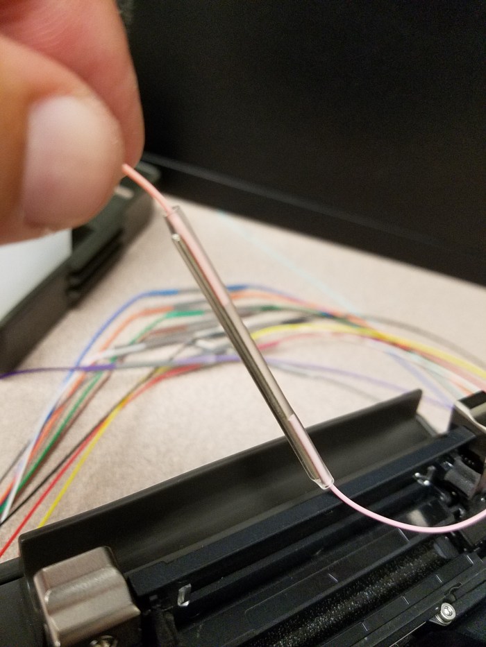
This is a basic fiber strand before removing the cladding.
 The fiber has been stripped of its cladding and inserted into the fiber holder.
 The fiber holder is inserted into the cutter and processed. This device cuts the fiber/glass at the desired length and stores the cut pieces into its integrated trash/storage bin.
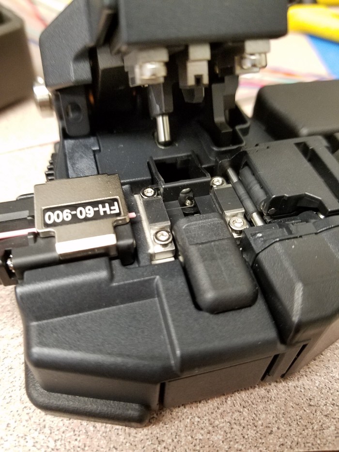 The fiber strand has been cut and disposed of properly as you can see here. Now it is ready to be placed into the fusing device.
 Both ends of the fiber to be fusion spliced, have been prepped and remain in their fiber holder. They are placed into the fusion splicer and set to be fused.
 The fiber splicer lid is closed and set to fuse the two strands. It will align and fuse the fiber automatically. Once it is fused via the electrodes, it will run a test on the dB loss within the fuse itself. Next step includes opening the fusion splicer and carefully removing the exposed fiber strand(now one piece).
 The pre-installed heat shrink tube in then slipped over the new splice(very carefully) and inserted into the heater portion. It then runs a process of heating the sleeve and bonding it to the new splice section. This sleeve also includes a thin metal rod/shaft to protect the fresh splice from bending.
 The freshly spliced section of fiber is finished and its corresponding tale/connector is ready to be installed.
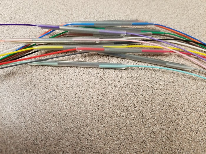 This a 6 pair/12 strand fiber bundle that has been successfully fusion spliced.
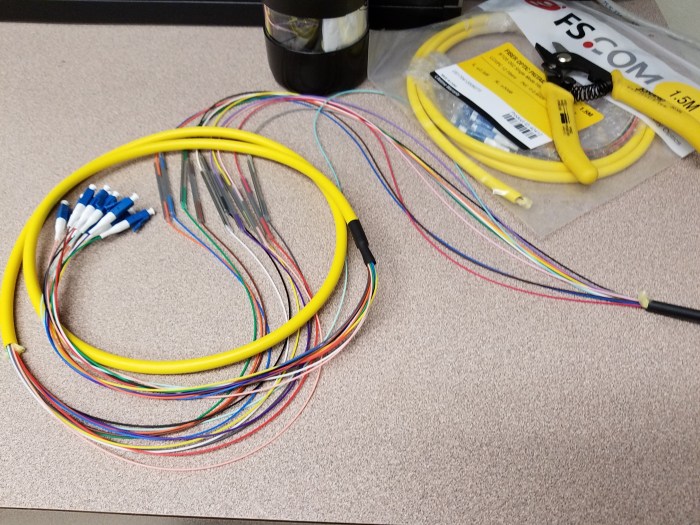 These FS.COM pre-made splice tails make it easy to prep fiber for connection.
 The newly spliced fiber is ran into an enclosure and ready to be tested. This particular splice box is to be used for a PLC cabinet to connect to multiple other devices. This enclosure resides in an existing PLC cabinet. All fiber makeup should be done in standard color sequence as shown.
Easier than it looks.
This is a quick view into fusion fiber splicing. I have been asked on many occasions to show the process. If you have any further questions feel free to reach out, like and comment. Thanks for stopping by!
